- #PROGRAMA SERVO MOTOR ARDUINO HOW TO#
- #PROGRAMA SERVO MOTOR ARDUINO INSTALL#
- #PROGRAMA SERVO MOTOR ARDUINO ANDROID#
- #PROGRAMA SERVO MOTOR ARDUINO SOFTWARE#
- #PROGRAMA SERVO MOTOR ARDUINO CODE#
In this case, I called the servo ‘myservo’ but you can use other names as well.
Include the servo library: includeYou can also find this library under Sketch > Include Library > Servo. Interesting enough, there are some comments in portuguese language (I’m a brazilian guy) in the file spindle_control./* * Created by ArduinoGetStarted. The first step is to include the required Arduino library.
#PROGRAMA SERVO MOTOR ARDUINO INSTALL#
TODO: Install the optional capability for frequency-based output for servos.

The pinage and registers of Atmega are defined there.Īnd if you open and look the file spindle_control.c, in line 89, 90 and 91: Once it reaches 180 degree, it is programmed to rotate back to 10 degree step by step. In the first for loop, motor shaft is rotated from 10 degrees to 180 degrees step by step with a time delay of 15 milliseconds. MI GRBL Z-Axis servo controller this means the extension is installed successfully.Īre you realy sure the program doesn’t work with Arduino Mega? Please open the folder cpu_map and ther you will find the files: The position of the shaft is kept at 10 degrees by default and the Servo PWM input is connected to the 3rd pin of the Arduino Uno.

#PROGRAMA SERVO MOTOR ARDUINO SOFTWARE#
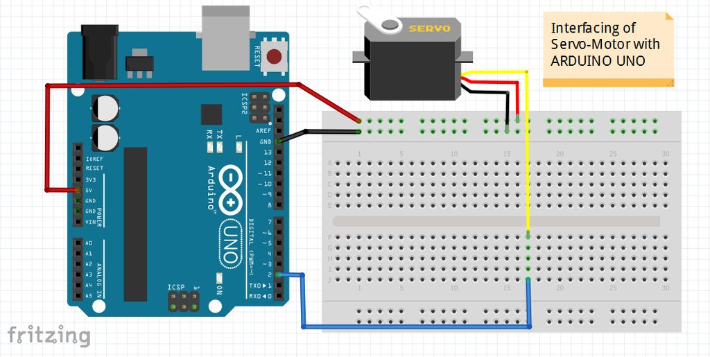
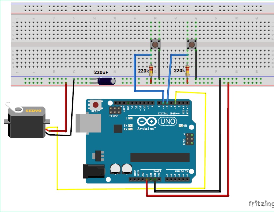
Now open the inkscape software got to extension tab you will see here Now got to C:\Program Files (x86)\Inkscape\share\extensions and paste here all the four files. Open the MIGRBL Inkscape extension folder copy all the four files. Now download the MIGRBL Inkscape extension unzip the downloaded file Installing MIGRBL extension in Inkscape softwareįirst of install the download inkscape version 0.48.5 software If you notice a problem like arduino get reset when servo moves so give external 5V DC supply to servo motor. In this way our wiring for GRBL CNC shield & servo motor. Eagle, Arduino ou Arduino Atmega microcontrolador, com servo motor. By reading the value of the potentiometer, we will know the rotation of the motor. In our case, this is achieved by mounting a potentiometer to the shaft of the motor. PWM signal wire of servo motor need to connect at Z+ pin GRBL CNC shield. (free/open source) cdigo do programa esto disponveis para Gambas, VB, NET. The key to controlling any servo is for the controller to know at any moment what the position of the horn is. Here you can see the actual implementation of. Schematic Diagram: Servo Motor Control using Arduino Simulation in Proteus. Simply connect the 5V & GND wire of servo motor to 5V and GND pin on CNC shield. Connect the red wire from the servo to the +5V pin on the Arduino Connect the yellow or white wire from the servo to a digital pin on the Arduino In proteus you don’t need to connect servo motor pins 1 and 3 in proteus. Connecting Servo motor to GRBL CNC shield GRBL CNC SHIELD AND SERVO MOTOR CONNECTION
#PROGRAMA SERVO MOTOR ARDUINO HOW TO#
In this way GRBL firmware is successfully uploaded to arduino, next we will see how to connect servo motor to GRBL CNC shield. Please note that GRBL will only work with arduino uno. Please delete if you already have any previous GRBL folder in Document>arduino>library folder. The power wire is typically red, and should be connected to the 5V pin on the Arduino/Seeeduino board.
#PROGRAMA SERVO MOTOR ARDUINO CODE#
Now open the MIGRBL folder go to exmple>grblUpload>grblUpload.inoĭouble click on grblUpload.ino to open the code just simply compile and upload the code to arduino.īe sure you have selected the correct port and board. The Servo has three wires: power, ground, and signal.

#PROGRAMA SERVO MOTOR ARDUINO ANDROID#
GRLB is the open source firmware freely available for every one, GRBL is used as firmware for CNC machine. Android Arduino Control: Arduino Bluetooth Servo Motor Control Arduino Bluetooth.


 0 kommentar(er)
